


 English
TURN-KEY PCB ASSEMBLY: BITTELE ELECTRONICS
PCB MANUFACTURING AND ASSEMBLY
Full Turn-Key PCB Manufacturer
You can quickly get quotes and order PCB fabrication and assembly using our online system. Take advantage of exclusive automatic discounts with our tool. Our BOM pricing tool ensures you receive the lowest price for your order.
START A TURN-KEY PCB ORDER
The Design Principles of Stencil Apertures
Solder paste printing is the important first step of the SMT assembly process because the quality of the printing directly affects the rate of SMT soldering defects. In the actual production process, we found that 60% - 70% of soldering defects are related to printing quality issues.The priority for small batch and mass production printing is the utilization of stencils made of stainless steel sheets. With laser cutting and electric polishing processes, stainless steel stencils can deliver high precision solder paste printing that’s well suited for fine pitch IC applications.
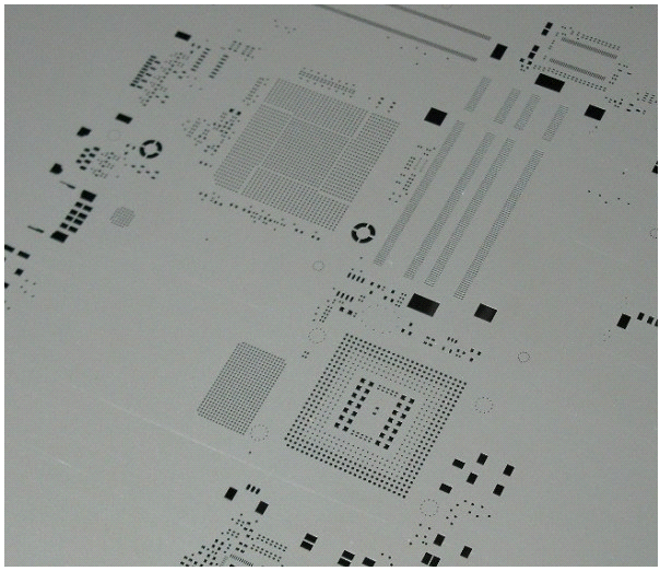
According to the IPC7525 industry standard, two parameters should be considered for determining stencil print performance:
•Aspect Ratio
The width of the aperture / thickness – the lowest acceptable ratio is 1.5.
(see blog article: Stencil thickness calculation)
•Area Ratio
Surface area of the aperture / surface area of the aperture walls – the lowest acceptable ratio is 0.66.
Since SMT component pad sizes are getting smaller and smaller, designers need to consider additional factors as well as their field experiences to ensure print quality. Here are some examples of aperture design considerations:
(1) When the pitch of an AFP,QFN and CSP is less than 0.5mm, the application of electric polishing to the stencil is required.
(2) Generally, the stencil open size is a 1:1 scale with pads sized for lead free soldering. However, there are other considerations if BGA and QFN/QFP ICs are involved.
(2-1) If the BGA pitch >1.0mm, then the aperture size should be a 1:1 scale opening.
(2-2) If the BGA pitch <0.5mm, then the aperture size should be 95% of the pad’s size.
(2-3) For a 0.4mm pitch QFP, the aperture width should be 85%, length 110% (extended).
(2-4) For a 0.65 SOP, the aperture width should be 90%.
(2-5) For an SOT with big pads, the aperature width should be 110%; for small pads, the aperature width should be 100%, length 110% extended.
(2-6) For an SOT89 with small pads, the width should be extended 0.5mm.
(2-7) SOT252 -- big pads need to make small aperture grids
(2-8) For a QFN aperture design, please see the blog article: Stencil aperture consideration for QFN chips
Related Articles:
Please briefly describe the information you are seeking in the search bar below.